Manual Calibration Guide for XTCERA 580DC Machine
TABLE OF CONTENTS
- Introduction
- 1. Tools Required
- 2. Calibrating the X/Z Axis
- 3. Calibrating the A Axis
- 4. Calibrating the Y Axis
- 5. Calibrating the Rotation Axis
- 6. Perform a Test Mill
Introduction
The XTCERA 580DC Manual Calibration Guide is designed to assist users to calibrate the XTCERA 580DC milling machine. Manual calibration involves adjusting the machine's settings to ensure precise milling and optimal performance. This process is essential if any discrepancies in milling are observed.
The Manual calibration is used if the Auto calibration is unsuccessful. This process involves careful measurements and adjustments of various axes (X, Y, Z, and A) to align the machine components correctly.
This guide provides a step-by-step instruction on how to perform a manual calibration, ensuring that users can maintain the accuracy and reliability of the XTCERA 580DC. By following this guide, users can enhance the machine's performance and prolong its lifespan.
1. Tools Required
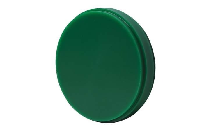
Wax blank (D98-12mm)
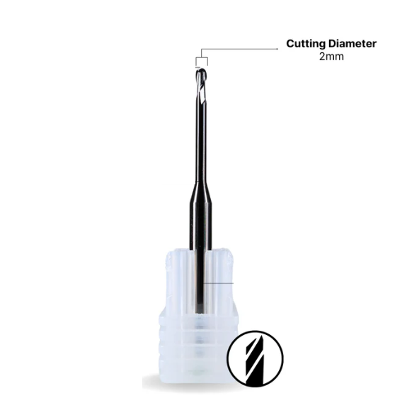
2mm Carbide tool assigned to T1 and securely in the collet
Working iTool3_3105 application
2. Calibrating the X/Z Axis
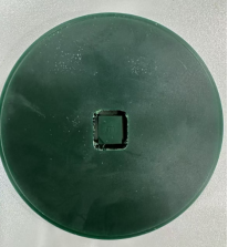
Insert the wax blank (D98-12mm) into the clamp.
Ensure that T1 (2mm) is securely in the collet. Carbide tools are acceptable.
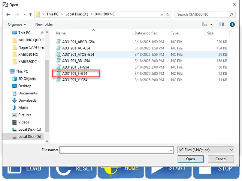
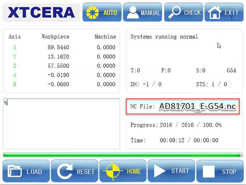
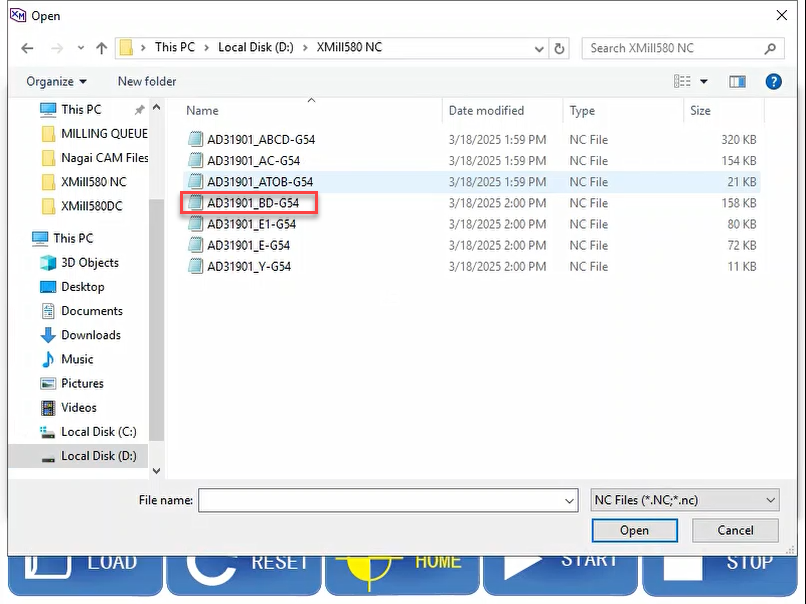
Load the file “AD*****_E-G54.nc” from the “XMill580 NC” folder on disk D.
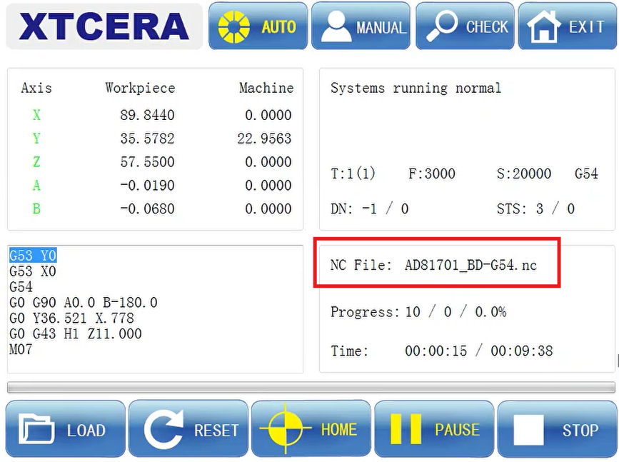
Click ‘Start’ to begin milling.
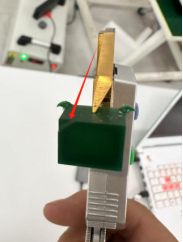
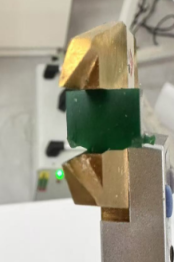
Measure S1 (side with the dent) and S2 (opposite side).

The standard data for S1 and S2 is 0.98-1.03.
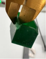
Measure Z (thickness of the block/cube).
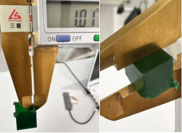
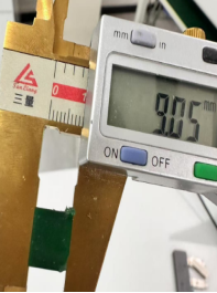
The standard data for Z is 8.98-9.05.
Reference Video: How to Measure S1, S2 and Z
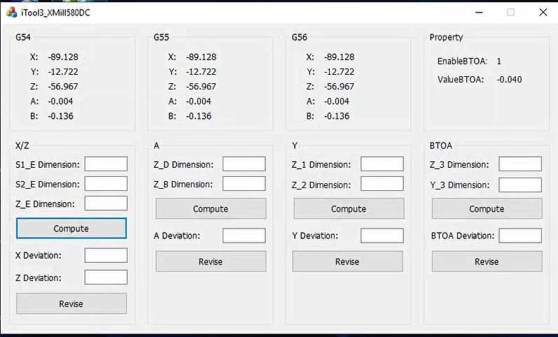
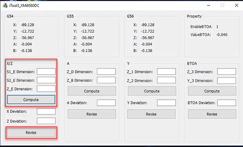
Open the iTool3_3105 application.
Take a screenshot of the initial values before inputting any data.
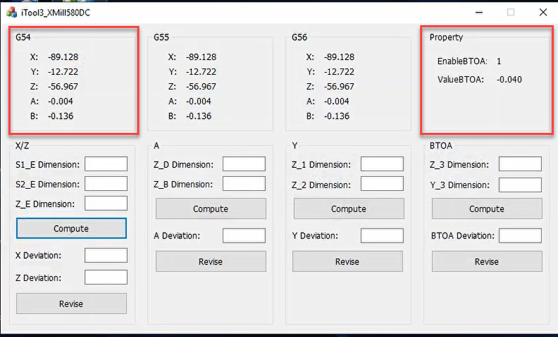
Input the measured data into the application and click “Compute” and then “Revise.”
Restart the machine software.
3. Calibrating the A Axis
Load the file “AD*****_BD-G54.nc” from the “XMill580 NC” folder on disk D.
Click ‘Start’ to begin milling.
Measure the T about the B and D cubes.
Note: If the data for B and D are similar, the A axis is considered vertical.
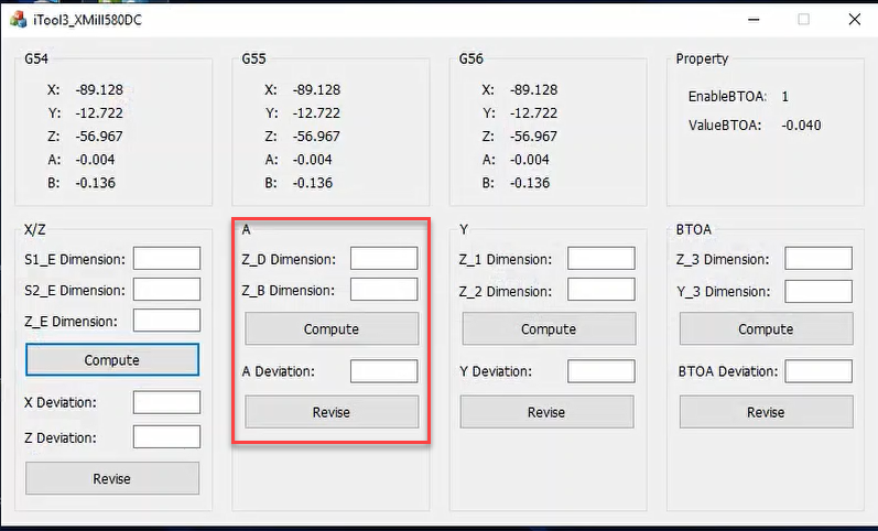
Open the iTool3_3105 application.

Input the measurement data into the application and click “Compute” and then “Revise.”
Restart the machine software.
4. Calibrating the Y Axis
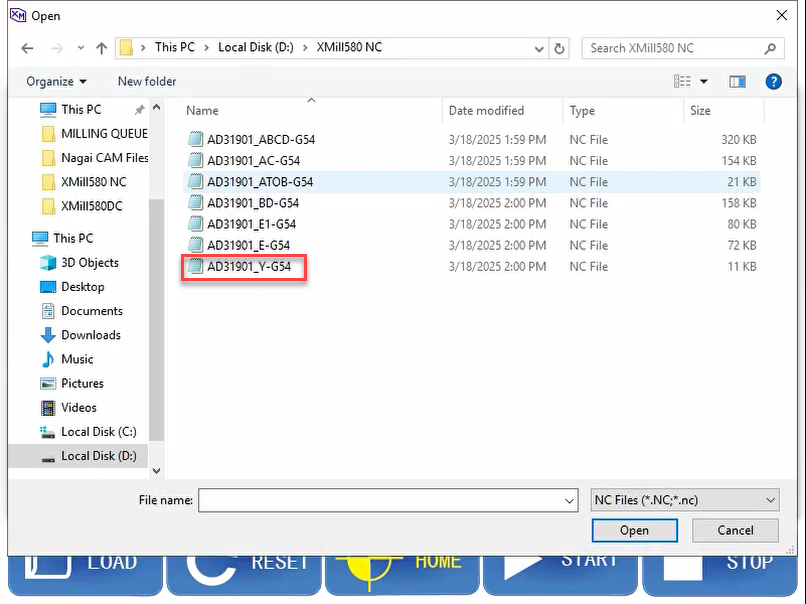
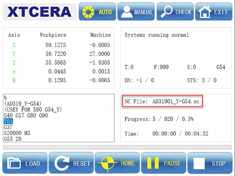
Load the file “AD*****_Y-G54.nc” from the “XMill580 NC” folder on disk D.
Click ‘Start’ to begin milling.
Measure Y1 and Y2.
The standard data for Y is 7.40.
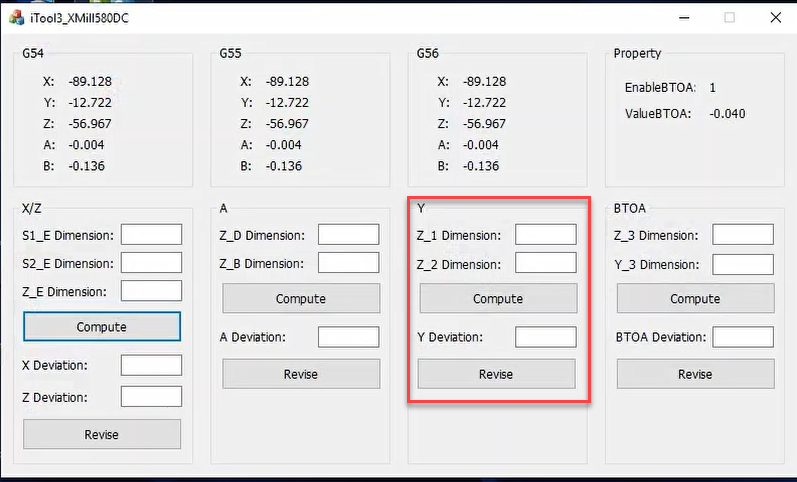
Open the iTool3_3105 application.

Input the measurement data into the application and click “Compute” and then “Revise.”
Restart the machine software.
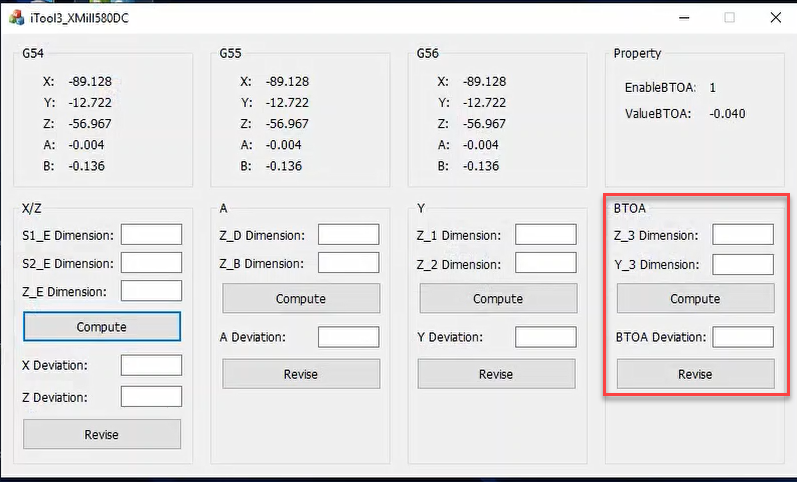
5. Calibrating the Rotation Axis
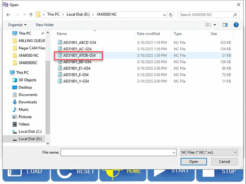
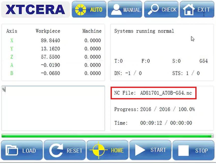
Load the file “AD*****_ATOB-G54.nc” from the “XMill580 NC” folder on disk D.
Flip/rotate the wax after calibrating Y and BEFORE milling the ATOB-G54 nc file. The ATOB cube and Y cube are in the same position.
Click ‘Start’ to start milling.
Note that the cube may fall off during milling; this is normal.
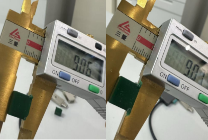
Measure Z3.
The standard data is 8.0
Measure Y3.
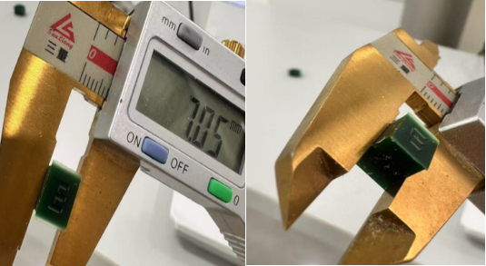
The standard data is 7.0
Open the iTool3_3105 application.

Input the measurement data into the application and click “Compute” and then “Revise.”
Restart the machine software.
6. Perform a Test Mill
Conduct a test mill using a single crown.
Verify the results to ensure calibration accuracy.
Was this article helpful?
That’s Great!
Thank you for your feedback
Sorry! We couldn't be helpful
Thank you for your feedback
Feedback sent
We appreciate your effort and will try to fix the article