TABLE OF CONTENTS
- Color coding on import
- Connection menu overview
- Identify Interface
- Export Interface and Extract
- Replace Interface
- Quick checklist
- Need Further Help?
Interface geometry can affect both calculation time and the quality of screw channels on anatomic abutment bridges, full arches, and All-on-X cases. MillBox gives you connection tools that identify, correct, export, and replace interfaces so you get consistent, reliable results.
Color coding on import
MillBox color-codes implant interfaces when you import the STL.
Orange means Internal
Cyan means External
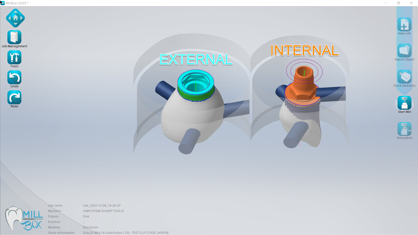
Figure 1. Interface recognition on import. Cyan shows External. Orange shows Internal.
Connection menu overview
Open Tools then Connections to manage implant interfaces. From here you can:
Identify Interface
Export Interface and Extract geometry
Replace Interface using library parts or saved presets
Identify Interface
Sometimes the interface area is detected incorrectly. This can slow calculations or create poor screw-channel results. Use Identify to redraw the interface with cylinders so only the true seating area is marked.

Figure 2. Identify Interface view. Left shows the interface area correctly designated in cyan using the cylinder tool. The right shows the raw STL rim and irregular edges that can cause slow calculations or poor screw-channel results.
How to use Identify
Go to Tools > Connections > Identify
Place the cylinder over the interface seat
Adjust diameter and height to match the connection
Confirm and re-calculate
Tip: Keep the cylinder just large enough to cover the interface seat. Oversizing can remove needed wall thickness.
Export Interface and Extract
Use Export Interface to capture the connection geometry from an imported object. This is helpful when you do not yet have a MillBox library item for that part.
Export Interface saves the current interface geometry
Extract lets you clean or tweak the geometry, then save it as a preset for the Replace workflow
Replace Interface
Replace swaps the detected interface with a known, validated library item. You can run it manually or let MillBox match automatically.
Why use Replace
Consistent, known geometry across cases
Less variation from mixed CAD libraries
Better fit and fewer toolpath problems
Quick checklist
Correct color on import: cyan for External, orange for Internal
If recognition looks wrong, run Identify and redraw the seat
Save good geometry with Export or Extract
Standardize production with Replace using library parts
Recalculate and run Simulation before milling
For deeper details, see the MillBox online manual: https://help.cimsystem.com/millbox-online-manual-23
Need Further Help?
Need help validating your CAD export settings or confirming your MillBox build supports this option? Email support@levelupcadcam.com.
Was this article helpful?
That’s Great!
Thank you for your feedback
Sorry! We couldn't be helpful
Thank you for your feedback
Feedback sent
We appreciate your effort and will try to fix the article